
Supplier-coordinated electromechanical integration
Electronics Assembly & Functional Testing
Coordinate PCBA, wire harnesses, connectors, mechanical integration, box build, functional testing, documentation, and delivery through a controlled project baseline.
Typical scope
PCBA · harness · box build · testControl baseline
BOM · files · firmware · test limitsIntegration focus
Electrical, mechanical, and supplier interfaces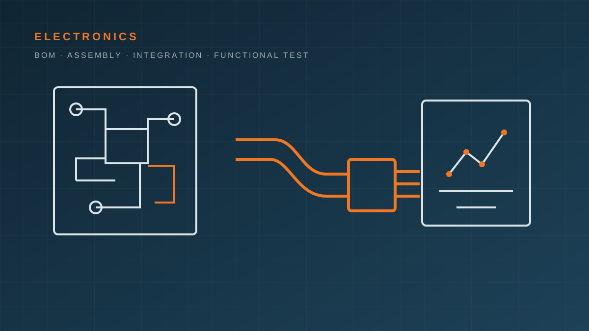
Electronics and mechanics must be controlled as one build
For a product containing a planetary gearmotor, PCB, wire harness, sensors, plastic or metal housing, and moving mechanism, many failures occur between supplier scopes rather than inside one component. A correct PCB can still fail the product if the connector is reversed, the harness is too short, firmware is mismatched, the enclosure traps heat, or the functional test does not exercise the real load.
KEY-CRON coordinates those interfaces and the relevant manufacturing partners. We do not present every electronics process as an owned factory. The PCBA or assembly supplier, manufacturing site, equipment, quality system, certification scope, capacity, and process evidence are confirmed for the specific program.
Possible project scope
A project may include:
- bare PCB fabrication and component procurement through an approved supplier route;
- SMT and through-hole assembly, selective or hand operations where specified;
- programming, serialization, labeling, and controlled firmware loading;
- wire cutting, stripping, crimping, connector assembly, continuity, and pull-force checks;
- integration of PCBAs, harnesses, gearmotors, sensors, switches, plastic parts, and metal structures;
- torque-controlled fastening, adhesives, thermal interfaces, sealing, and cosmetic assembly;
- in-circuit, programming, continuity, functional, burn-in, or other defined tests;
- packing, traceability, inspection records, and shipment coordination.
The final scope is established by drawings, BOM, risk, volume, applicable workmanship or regulatory requirements, and the selected supplier’s actual capability.
Build-package control
BOM and approved parts
The BOM should contain manufacturer part numbers, descriptions, quantities, reference designators, approved alternatives, DNP status, customer-supplied parts, lifecycle information where relevant, and a visible revision. Distributor stock or a lower-cost “equivalent” does not authorize substitution.
Define who may approve an alternate and what evidence is required. For sensitive parts, sourcing channels, date codes, traceability, storage, moisture sensitivity, or counterfeit mitigation may need project-specific controls.
Manufacturing data
Align Gerber or ODB++, drill data, board fabrication drawing, stack-up, assembly drawing, centroid data, stencil notes, schematic, test points, and panel requirements. Files with conflicting revisions should stop the build rather than be resolved by informal guesswork.
Firmware and programming
Specify firmware name and checksum or version, programming stage, programming interface, configuration data, serialization, logs, security restrictions, and rework/update policy. If keys or credentials are involved, agree who generates, transfers, loads, stores, and audits them.
Harness and electromechanical interfaces
Control wire specification, color, length, strip length, crimp terminal, connector, pinout, splice, sleeve, label, routing, bend radius, retention, and continuity test. Mechanical CAD should define clearances, mounting, grounding, shielding, thermal paths, fasteners, torque, adhesive, and sealing interfaces.
DFM, DFA, and DFT before the first build
A practical review should examine:
- component availability, lifecycle, approved alternatives, and lead-time risk;
- PCB manufacturability, panelization, assembly access, polarity, and marking;
- programming and test-point access;
- connector keying, pinout, harness routing, strain relief, and serviceability;
- enclosure clearance, thermal behavior, grounding, shielding, and assembly order;
- rework access and how a failed unit will be diagnosed;
- whether the proposed test actually detects the important failure modes.
The output should be a decision log: accepted changes, open questions, responsible owner, and the revision released for quotation or build.
Prototype and first-article path
- Input and revision review: identify released, draft, missing, and customer-supplied items.
- Supplier and sourcing plan: match process, quantity, workmanship, traceability, compliance, and timing.
- DFM/DFA/DFT review: close build and test questions before material commitment.
- Pilot build: record programming, assembly, rework, fixture, and test learning.
- First-article approval: review workmanship, dimensions, interfaces, function, records, and deviations.
- Controlled baseline: freeze BOM, files, firmware, work instructions, test limits, packing, and change authority.
- Production and delivery: monitor agreed quality checkpoints and preserve lot or serial traceability as required.
Functional test must have a specification
“Power on and check” is not a sufficient test definition. For each function, specify:
- stimulus, load, input voltage, environment, and precondition;
- measured signal, response, tolerance, timing, and units;
- fixture, software, calibration, reference unit, and operator action;
- pass/fail logic, retry and rework rules, data storage, and required report;
- product revision, firmware version, serial or lot identity, and test-program version.
The test depth should match product risk and failure modes. A simple continuity test, an end-of-line functional test, and a regulatory compliance test answer different questions.
Documentation and approval boundaries
Possible delivery records include BOM and revision confirmation, component or material records, programming logs, first-article results, workmanship inspection, functional-test data, nonconformance and rework records, serial or lot traceability, packing list, and agreed compliance declarations.
Required documents must be named in the quotation and quality plan. RoHS, REACH, IPC workmanship class, PPAP, FMEA, regulatory testing, or customer-specific forms are not automatic inclusions. Current supplier certificates must be checked for entity, site, scope, and validity before being represented as project evidence.
KEY-CRON is best suited to small and mid-sized product teams that need direct English engineering communication across electronics, mechanics, motion components, and several Pearl River Delta suppliers. A mature, very high-volume PCBA-only program may be more efficiently purchased directly from a nominated electronics factory.
Connected paths
Place this capability inside the full project path.
Small Western teams rarely buy one isolated process. They balance the motion system, structural parts, electronics, testing, and delivery. These entry points help you continue from the right angle.
Prepare an electronics build
Define the build package and the testable result.
The first review can begin before every file is final. Identify released documents, draft items, customer-supplied parts, and the decisions that still require engineering work.
- Controlled BOM with manufacturer part numbers, approved alternatives, DNP status, and revision
- Gerber or ODB++, fabrication drawing, pick-and-place data, assembly drawing, and schematic as applicable
- Firmware version, programming method, security or key-handling restrictions, and update process
- Harness drawing, connector and pinout definition, crimp or pull-force requirements, and wire routing
- Mechanical CAD, assembly sequence, torque, adhesive, thermal, grounding, sealing, and cosmetic requirements
- Functional test method, fixture responsibility, pass/fail limits, records, traceability, quantity, packing, and timing
Related paths
FAQ
Questions to clarify before scoping this capability.
Does KEY-CRON operate its own PCBA factory?
KEY-CRON coordinates electronics manufacturing partners and the interfaces around the complete product. The actual PCBA supplier, process, equipment, quality system, capacity, and certification scope are selected and confirmed for the project.
What files are needed for a PCBA or box-build quotation?
Typical inputs include a controlled BOM, Gerber or ODB++, fabrication and assembly drawings, centroid or pick-and-place data, schematic where needed, firmware and programming instructions, harness drawings, mechanical CAD, test requirements, quantity, and timing.
Can you purchase components and manage substitutions?
Component sourcing can be coordinated, but approved manufacturers, alternates, lifecycle risk, customer-supplied parts, and substitution authority must be defined. No component change should be made outside the agreed approval process.
Do you support functional testing and test fixtures?
Functional testing can be coordinated when the customer defines the function, interfaces, pass/fail limits, required records, and fixture responsibility. Fixture design and validation are separate project tasks unless included in the agreed scope.
Does a passing functional test guarantee regulatory compliance?
No. A project functional test verifies defined product behavior. EMC, electrical safety, radio, environmental, medical, automotive, or other regulatory compliance requires its own applicable standards, qualified laboratories, evidence, and approval path.