
Core product family
DC Planetary Gearmotors & Gearboxes
DC planetary gearmotors and gearboxes: 28 mm tailgate strut platform, 10–42 mm standard range, custom interfaces, validation, and production coordination.
Flagship application platform
28 mm tailgate strut gearmotorPublished standard reference
10–42 mm all-metal planetary rangeEngineering path
Operating point · interfaces · validation · release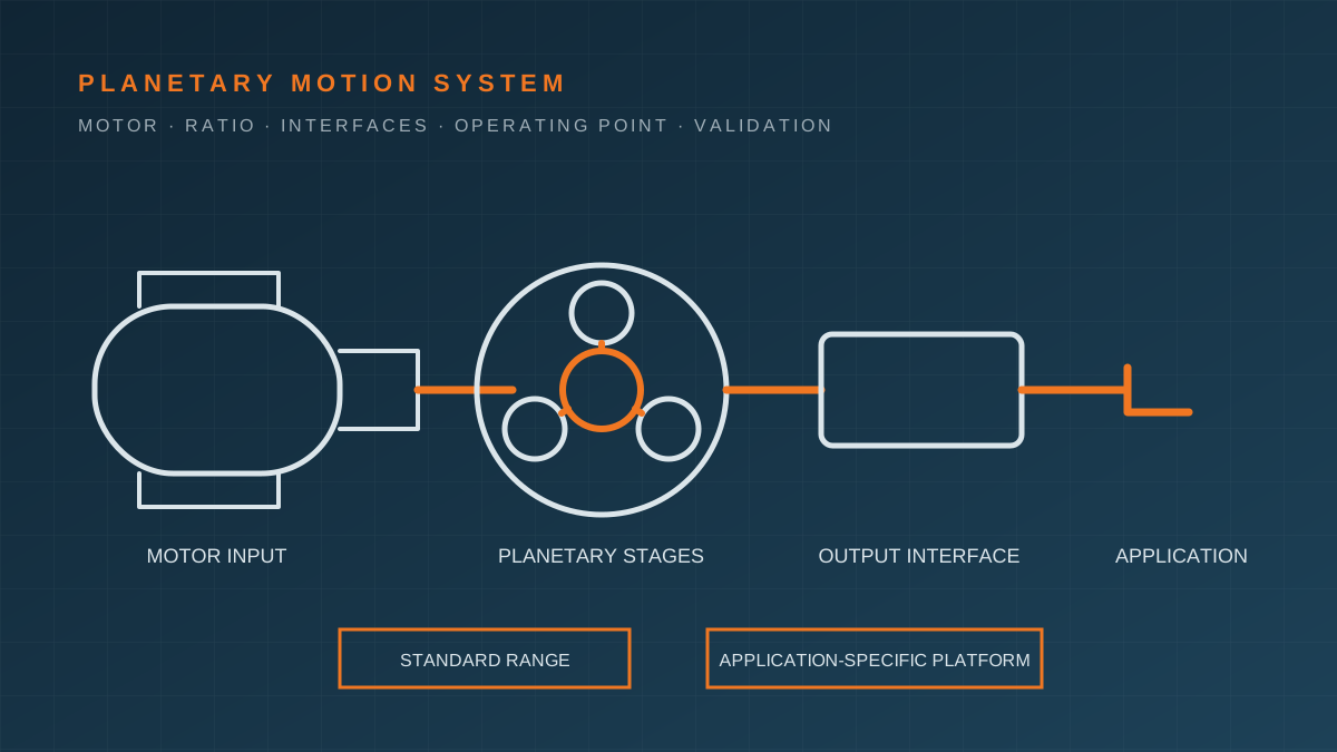
The product family has two starting paths
Application-specific platform
The 28 mm tailgate strut planetary gearmotor is KEY-CRON’s flagship focus. It starts from a defined package and application direction, then confirms ratio, motor direction, output coupling, wire and connector, mounting, controller interface, movement, current, noise, temperature, endurance, and system approval around the actual strut program.
Standard reference range
The 10–42 mm all-metal planetary series provides published diameter, voltage, power, ratio, speed, torque, and length references for preliminary screening. It is not one universal configuration: each diameter contains motor and ratio combinations with different working points and limits.
If neither path fits, the project can define a modified standard configuration or a more application-specific program. Feasibility, non-recurring work, tooling, MOQ, samples, validation, and timing are then scoped explicitly.
Select the complete motion system
1. Start at the mechanism
Define what moves, how motion reaches the load, and where the worst operating point occurs. A direct shaft, belt, cable drum, lead screw, spindle, wheel, valve, or linkage converts gearmotor output differently. Include continuous, starting, peak, holding, shock, obstruction, and back-drive cases.
2. Establish speed and ratio
An initial ratio is the expected loaded motor speed divided by required output speed. The nearest available ratio must then be evaluated on the actual motor curve. Higher reduction generally lowers output speed and can increase available output torque, but may add stages, length, loss, backlash, noise, cost, and cycle time.
The ratio calculation guide explains the initial equations and screening steps.
3. Check torque with efficiency and gearbox limits
Ideal multiplication overstates output. Estimate with motor torque, total ratio, and configuration-specific efficiency, then check rated and time-limited gearbox torque, input speed, radial and axial load, bearing support, shock, stall, and holding conditions. Stall torque is not a continuous operating point.
4. Check current and thermal duty
Confirm voltage at the motor, controller current limit, starting and peak current, run/rest cycle, reversals, ambient temperature, enclosure, airflow or conduction path, and winding or gearbox temperature. A short successful movement does not prove repeated-cycle thermal suitability.
5. Define interfaces
The controlled interface may include:
- output shaft, D-flat, thread, spline, gear, coupling, or customer geometry;
- output bearing support, radial and axial load, retaining features, and lubrication boundary;
- mounting face, hole pattern, orientation, housing, seal, and adjacent parts;
- motor direction, leads, terminals, connector, pinout, wire length, routing, and strain relief;
- Hall sensor, encoder, switch, current sensing, or another feedback interface where applicable.
Interface customization is not only a drawing change. It may affect tooling, component sourcing, assembly, inspection, balance, sealing, noise, capacity, and MOQ.
Validation must use defined conditions
Performance
Measure speed, torque or force, current, efficiency where required, movement time, holding, start, obstruction, and back-drive under agreed voltage, load, temperature, mechanism position, and controller behavior.
Acoustics and feel
Define airborne or structure-borne noise, distance, mounting, background, load, speed, travel position, temperature, equipment, processing, and pass/fail value. Also consider vibration, backlash, torque ripple, and perceived smoothness.
Thermal and endurance
Define cycle profile, run/rest time, direction changes, load distribution, voltage, temperature, orientation, lubrication condition, inspection interval, allowable drift, and failure criteria. Accelerated tests require a stated relationship to the intended use.
Environmental and interfaces
Depending on the product, confirm temperature and humidity exposure, vibration, shock, dust/water boundary, corrosion, chemicals, wire retention, connector, mounting, output interface, packaging, and transport.
Production release evidence
The release package is project-specific and may include:
- product datasheet and released dimensional/interface drawing;
- approved motor, ratio, shaft, connector, wire, mounting, and direction;
- incoming, in-process, functional, torque, current, noise, or final-inspection records;
- material, component, RoHS/REACH, or other agreed declarations;
- approved sample, boundary sample, test report, serial or lot traceability, and packing list;
- PPAP, FMEA, control plan, capability, or customer-specific records when contracted.
These documents are not automatic. Name required evidence before quotation and sample release.
Manufacturing relationship and certification boundary
KEY-CRON is the product and project coordination contact. Manufacturing may be performed by the long-term Zhuhai partner or another approved source matched to the model and scope. Before representing a certification or capability, verify the legal entity, production site, process, model, certificate scope, validity, and any subcontracting relevant to the project.
Factory management-system certification does not certify a gearmotor for an application. The customer retains final product and application approval unless a different responsibility is explicitly contracted.
When the gearmotor is only one component
KEY-CRON can coordinate molded gears and housings, mold tooling, metal brackets, wire harnesses, electronics, functional testing, assembly, packing, and delivery around the primary motion component. The advantage for a small Western team is a direct English engineering path across those interfaces—not an assumption that every adjacent task is included without scope.
Connected paths
Place this capability inside the full project path.
Small Western teams rarely buy one isolated process. They balance the motion system, structural parts, electronics, testing, and delivery. These entry points help you continue from the right angle.
Start a gearmotor review
Define the motion system before choosing a ratio.
A part number is the output of the selection—not the first input. Send the conditions you know and mark values that still need engineering work.
- Application, mechanism drawing, target movement, travel, cycle time, and load path
- Nominal and operating voltage, controller current limit, motor control, direction, braking, and feedback
- Target output speed, continuous load, start and peak torque or force, inertia, holding, shock, and back-drive
- Duty cycle, starts, reversals, expected life, temperature, humidity, vibration, dust/water, corrosion, and mounting orientation
- Available diameter and length, mounting, output shaft/spline/coupling, bearing support, housing, wire, connector, and pinout
- Noise, backlash, efficiency, thermal, functional, reliability, traceability, documentation, quantity, and timing requirements
Related paths
28 mm tailgate strut platform
Review the flagship product platform, interfaces, validation path, and inquiry checklist.
Explore →Tailgate strut application guide
See how the gearmotor connects to the spindle, controller, vehicle mechanism, and validation conditions.
Explore →Standard 10–42 mm range
Use published brochure data for preliminary diameter and ratio screening.
Explore →Ratio calculation guide
Calculate an initial ratio, then screen efficiency, current, thermal duty, packaging, and tests.
Explore →FAQ
Questions to clarify before scoping this capability.
What is the difference between a planetary gearbox and a planetary gearmotor?
A planetary gearbox is the reduction assembly. A planetary gearmotor combines a motor and gearbox, often with project-specific output, wiring, connector, mounting, feedback, or housing interfaces. Performance must be evaluated for the complete configuration.
How do I choose the right ratio?
Start with loaded motor speed and required output speed, then check required output torque, gearbox efficiency, motor curve, current, temperature, duty cycle, gearbox limits, package, and available ratios. Final selection requires application testing.
Can shaft, spline, connector, wire, housing, and mounting be customized?
These interfaces can be reviewed and adapted subject to technical and commercial feasibility. The released drawing should define geometry, tolerances, materials, finish, pinout, direction, wire length, mounting, and verification.
Are the 10–42 mm catalog values guaranteed for my application?
No. They are published reference data for preliminary screening. Availability, motor and ratio combination, dimensions, current, torque, speed, noise, life, interfaces, and environmental suitability must be confirmed for the selected model and use case.
How are noise and lifetime requirements handled?
Define the load, speed, voltage, distance, mounting, background noise, temperature, duty cycle, cycle profile, and pass/fail method. Noise and endurance results only have meaning when tied to stated conditions and the released configuration.
Who manufactures the gearmotors?
KEY-CRON coordinates the product and delivery path with long-term manufacturing partners, including AIMO in Zhuhai for documented gearbox, tooling, molding, assembly, and test resources. The legal manufacturer, site, model, scope, and applicable certification are confirmed for each project.