
Article
Injection Mold Design Process: From DFM to Tool Release
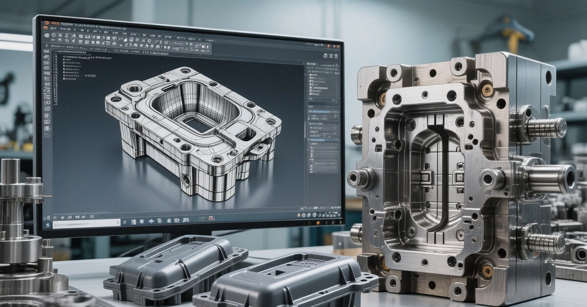
Injection mold design connects the released plastic-part definition to a tool that can be built, maintained, sampled, and used repeatedly. A complete process includes more than 3D mold construction: inputs, assumptions, approval points, trial evidence, corrections, and production handover all need control.
1. Confirm the design inputs
Before detailed mold design, align:
- released 3D product model and dimensioned drawing;
- resin manufacturer, grade, color, additives, and shrinkage basis;
- annual and lifetime volume;
- target molding machine, shot size, tie-bar spacing, and available interfaces;
- cavity count, cycle-time objective, and automation expectations;
- appearance surfaces, texture, gate restrictions, and allowable witness marks;
- critical dimensions, measurement conditions, and mating parts;
- tool ownership, tool life, spare parts, and maintenance expectations.
Unresolved DFM items should remain visible in an action list. Starting detailed design while critical inputs continue changing usually transfers uncertainty into steel.
2. Develop the mold concept
The mold concept sets the architecture before individual plates and components are finalized.
Key decisions include:
- cavity layout and mold orientation;
- parting surface and shutoff strategy;
- cold runner, hot runner, or another feed system;
- gate type, location, balance, vestige, and removal;
- primary ejection approach;
- slides, lifters, unscrewing, collapsible cores, or insert loading;
- preliminary cooling and venting;
- expected mold size and machine compatibility.
For complex parts, filling, packing, cooling, or warpage analysis may support the concept. Simulation results depend on correct resin data, geometry, and process assumptions, so they should be treated as engineering evidence rather than decoration.
3. Complete the detailed design
Detailed design converts the approved concept into buildable components and assemblies.
The design normally covers:
- mold base, cavity and core inserts;
- runners, gates, sprue handling, and hot-runner interfaces;
- slides, lifters, angle pins, locks, and wear components;
- ejector pins, sleeves, stripper systems, return mechanisms, and sensors;
- cooling channels, baffles, bubblers, connectors, and sealing;
- vent locations and overflow or vacuum provisions where needed;
- guide, locating, support, and clamping elements;
- replaceable inserts at high-wear or modification-prone areas;
- material, hardness, heat treatment, surface finish, and coatings;
- part and cavity identification, date stamps, and traceability features.
Clearances, travel, interference, assembly access, lubrication, and maintenance should be checked in the full mold assembly—not only on isolated components.
4. Review and approve the design
Before machining critical steel, conduct a structured review with product, tooling, molding, and quality inputs.
The review should confirm:
- correct product revision and shrinkage application;
- gate, parting, ejector, and mechanism marks on the product;
- filling, venting, cooling, and release risks;
- critical dimensions and steel-safe strategy;
- sensor and machine-interface requirements;
- tool access, assembly, maintenance, and spare parts;
- accepted deviations and remaining open actions.
Customer approval should be recorded against identifiable drawings or review files. “Approved in a meeting” is difficult to control after later revisions.
5. Manufacture, inspect, and assemble the tool
Machining may combine CNC milling, EDM, wire cutting, grinding, drilling, fitting, polishing, texturing, and heat treatment. The exact route depends on geometry, steel, accuracy, finish, and tool architecture.
During manufacture:
- inspect critical inserts and interfaces before final assembly;
- track heat-treatment and surface-treatment status;
- control electrode, insert, and drawing revisions;
- verify water circuits and sealing;
- check mechanism movement, stroke, and interference;
- record purchased-component specifications;
- perform a dry-cycle or bench check where appropriate.
Toolmaking evidence should be proportionate to project risk and agreed documentation requirements.
6. Run trials and close findings
The first trial is a learning event, not an automatic production approval.
Review:
- filling pattern, short shots, flash, burns, weld lines, and trapped air;
- ejection, sticking, deformation, scratches, and witness marks;
- dimensions after agreed conditioning;
- sink, voids, warpage, gloss, texture, and color;
- cycle stability, cooling balance, and mechanism operation;
- gate removal, automation, handling, and packing needs.
Separate process adjustments from tool corrections and product-design changes. Each action should have an owner, target date, affected revision, and verification result.
Subsequent trials should use controlled settings and clearly identified samples so that improvements can be compared.
7. Release the mold and production process
Tool completion requires more than an accepted sample. The handover package may include:
- approved part drawing and sample status;
- mold assembly and component drawings;
- bill of materials and purchased-part details;
- molding window or approved process parameters;
- inspection and validation reports;
- material and heat-treatment records where required;
- maintenance instructions and spare-parts list;
- waterline, electrical, hydraulic, pneumatic, and hot-runner information;
- tool location, ownership identification, and change history.
The exact documentation should be agreed before quotation because automotive, medical, consumer, prototype, and general industrial programs require different evidence.
A practical approval rule
Do not release machining because the schedule says design is finished. Release it when:
- the product revision and resin are identifiable;
- critical DFM decisions are closed or formally accepted;
- gate, parting, ejection, and visible marks are understood;
- the mold architecture matches the intended machine and volume;
- critical dimensions have a measurement and correction strategy;
- open risks, owners, and next decisions are recorded.
KEY-CRON coordinates mold tooling and DFM with precision injection molding and adjacent product interfaces where a project involves multiple suppliers.
Frequently asked questions
When should mold design start?
Detailed mold design should start after the product version, resin, expected volume, molding-machine constraints, appearance zones, critical dimensions, and major DFM actions are sufficiently defined. Open items should be recorded before tooling commitment.
What should a customer approve before mold machining?
Approval should cover the product revision, shrinkage basis, cavity and parting concept, gate and vestige, ejection marks, slides or lifters, major inserts, texture or appearance zones, and any accepted risks or open actions.
Does the first mold trial produce a final approved part?
Not normally. The first trial verifies filling, release, appearance, dimensions, tooling mechanisms, and process behavior. Findings may require process adjustment, steel correction, or product revision before approval.
For an initial review, send the current product files, resin, expected volume, appearance standard, and critical interfaces.