
Article
Injection Molding DFM: What to Review Before Tooling
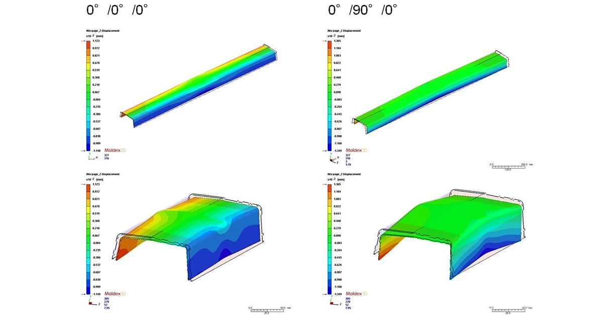
Injection molding DFM is the engineering review performed before a mold is committed. Its purpose is not to make every feature easy for the toolmaker. It is to find a practical balance between product function, appearance, tooling complexity, process stability, inspection, cost, and future changes.
A useful DFM review should end with decisions and open items—not only screenshots with red circles.
1. Start with product conditions and resin
The first material decision concerns the molded product resin, not the mold steel.
Define the service conditions:
- mechanical load, impact, wear, and expected life;
- operating temperature and exposure to moisture, chemicals, or UV;
- dimensional stability, creep, and friction requirements;
- appearance, color, texture, flame rating, food-contact, medical, or other compliance needs;
- whether glass fiber, mineral fill, lubricant, or another modifier is required.
Resin shrinkage and flow behavior influence dimensions, gate strategy, warpage risk, and tooling details. A generic material family such as “PA” or “PC/ABS” may be insufficient when grade-specific behavior matters.
Mold steel is a separate tooling decision based on expected volume, required finish, resin abrasiveness or corrosion, maintenance strategy, and tool-life expectations.
2. Review wall thickness and transitions
Large thickness changes can create different cooling rates, sink, voids, residual stress, and warpage. The right wall thickness depends on resin, flow length, geometry, and performance—it is not one universal number.
Review:
- nominal wall and local thick sections;
- gradual transitions rather than abrupt steps;
- coring of heavy bosses and structural masses;
- radii at load-bearing corners;
- whether ribs can provide stiffness more efficiently than solid material.
Simulation can support difficult geometries, but it does not replace accurate material data and a realistic process window.
3. Add draft and define cosmetic surfaces
Draft helps the part release without scuffing, distortion, or excessive ejector force. Required draft depends on depth, texture, resin, mold finish, and part geometry.
The DFM package should identify:
- primary pull direction;
- surfaces that need draft;
- texture and appearance zones;
- acceptable gate vestige, ejector marks, knit lines, and parting lines;
- areas where appearance takes priority over tooling simplicity.
If a zero-draft feature is functionally necessary, record the reason and the proposed release mechanism instead of silently accepting the risk.
4. Check ribs, bosses, clips, and undercuts
Ribs and bosses should support load without creating avoidable thick sections. Their proportions and connection radii need to be reviewed together with sink and filling risk.
Undercuts may require sliders, lifters, collapsible cores, unscrewing mechanisms, or a product redesign. Each mechanism affects:
- mold size and cost;
- cycle time and reliability;
- maintenance access;
- visible witness lines;
- future modification flexibility.
The lowest-cost answer is not always “remove every undercut.” The correct answer depends on product function and expected volume.
5. Set realistic tolerances and datums
Plastic dimensions move with resin shrinkage, moisture, temperature, fiber orientation, part geometry, and measurement conditions. Copying machined-part tolerances onto a molded drawing can create unnecessary tool corrections and inspection disputes.
Identify:
- functional datums and mating interfaces;
- critical dimensions and why they matter;
- measurement method, conditioning, and fixture;
- dimensions that can be controlled by the same mold feature;
- tolerance stacks across plastic, metal, gearmotor, PCB, and assembly interfaces.
Use tighter limits where function requires them, and allow a realistic process window elsewhere.
6. Review the proposed mold and molding process
Part DFM and mold concept should be reviewed together. Important items include:
- cavity count and layout;
- parting surface and shutoffs;
- gate type, location, vestige, and removal;
- filling balance and weld-line location;
- venting and trapped-air risk;
- ejector location and release sequence;
- cooling layout and likely hot spots;
- inserts, overmolding, threads, slides, and lifters;
- cavity identification and traceability.
For appearance-critical or dimensionally sensitive parts, the review should also define how trial results will be evaluated and which corrections remain possible.
7. Connect DFM to validation and commercial reality
DFM is incomplete if it ignores the intended production volume and approval route. A prototype tool, bridge tool, and long-life production mold may use different materials, cavity counts, automation assumptions, and validation depth.
Before tooling release, align:
- annual and lifetime volume;
- target tool life and ownership;
- sampling stages and approval responsibilities;
- dimensional, functional, appearance, and material evidence;
- packaging and handling requirements;
- expected engineering-change process;
- timing and commercial impact of unresolved items.
What a useful DFM package should contain
A practical output normally includes:
- marked-up views showing each issue;
- the risk or manufacturing reason behind it;
- a recommended change and, where useful, an alternative;
- items requiring customer decision;
- preliminary gate, parting, ejection, and mechanism concepts;
- an agreed list of critical dimensions and appearance zones;
- a revision-controlled action list before tooling release.
KEY-CRON can coordinate precision injection molding, mold tooling and DFM, and adjacent component interfaces for multi-part products.
Frequently asked questions
What files are needed for an injection molding DFM review?
A STEP or native 3D model is the best starting point. Add a dimensioned drawing, resin requirement, cosmetic standard, expected volume, mating-part information, and any critical functional or regulatory requirements.
Does DFM approval mean the molded part is production-approved?
No. DFM confirms that the design and proposed tooling approach are reasonable enough to proceed. Tool trials, dimensional results, functional tests, appearance review, and customer approval are still required.
Should the product resin and mold steel be selected together?
They are related but separate decisions. Product resin is selected around function, environment, compliance, appearance, and molding behavior. Mold steel and surface treatment are selected around tool life, resin wear or corrosion, finish, maintenance, and production volume.
To begin a review, send the current CAD, drawing, resin requirement, expected quantity, and open questions. The design does not need to be finished before the first engineering discussion.