
Article
How to Calculate a Planetary Gearmotor Ratio
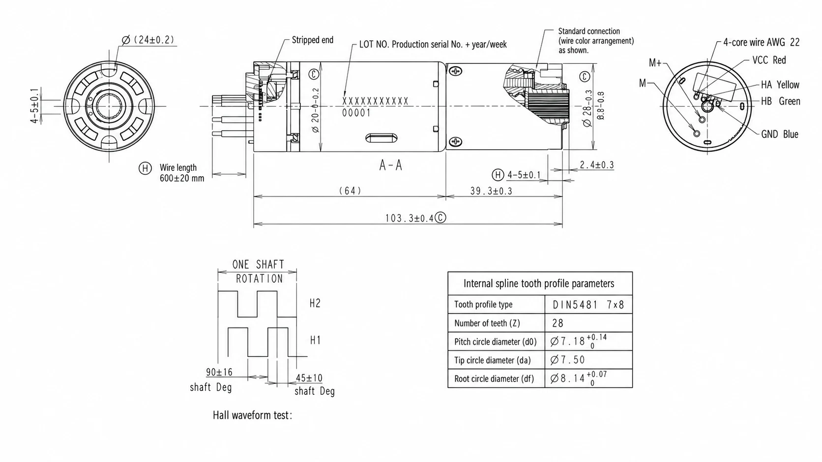
The first planetary gearmotor ratio can be estimated with simple equations. Selecting a production configuration requires more: the actual motor curve, gearbox efficiency, duty cycle, current limit, temperature, interfaces, and application testing.
This guide separates the initial calculation from the checks that determine whether a ratio is usable.
1. Define the output requirement
Start at the driven mechanism, not at a catalog motor. Establish:
- required output speed or movement time;
- continuous or repeated torque;
- starting, acceleration, holding, and peak torque;
- load inertia and any shock or back-driving;
- duty cycle and expected life.
For a linear actuator or automotive tailgate strut, convert the desired travel and cycle time into screw or gearbox output speed. Convert linear force through the screw, cable drum, or linkage geometry rather than using vehicle or door mass directly.
2. Calculate an initial speed ratio
Use the expected loaded motor speed, not only the catalog no-load speed:
i_initial = n_motor,loaded / n_output
Example: if the motor is expected to run near 6,000 RPM at the working load and the mechanism requires 120 RPM, the initial ratio is:
i_initial = 6,000 / 120 = 50:1
The nearest available ratios must then be evaluated. A nominal 48:1 or 52:1 option, for example, changes output speed and may move the motor to a different point on its torque–speed curve.
3. Estimate output torque with efficiency
The ideal multiplication T_motor × i overstates real output. Include the combined gearbox efficiency:
T_output,estimated = T_motor × i × η_total
Efficiency depends on gear geometry, number of stages, lubrication, load, speed, temperature, and manufacturing condition. Do not assume a generic efficiency value for final approval; use supplier data for the candidate configuration.
Rearranging the relationship gives the approximate motor torque required:
T_motor,required = T_output,required / (i × η_total)
That motor torque must be checked against the motor curve at the intended voltage and speed—not against stall torque as a continuous operating point.
4. Keep continuous and peak conditions separate
Create a small load-case table for:
- normal movement;
- start or breakaway;
- maximum geometry or load point;
- holding or back-driving;
- obstruction or stall response.
For each case, record duration, frequency, output speed, output torque, motor current, and acceptance condition. This avoids selecting a gearbox around one dramatic but very brief peak while overlooking repeated thermal load.
5. Check motor current and temperature
A ratio changes the torque demanded from the motor and therefore affects current and heat. Confirm:
- voltage at the motor under wiring and controller losses;
- running, starting, and peak current;
- controller current limit and protection behavior;
- run/rest cycle and winding temperature;
- ambient temperature and available cooling path.
A configuration that passes a short bench movement can still fail a repeated-cycle thermal test.
6. Check gearbox limits and packaging
Screen the candidate ratio against rated and short-duration torque, allowable radial and axial loads, backlash, noise, input speed, output bearing support, and life. More stages may increase ratio but also change length, mass, losses, torsional behavior, and cost.
Verify the complete envelope: gearbox diameter, overall length, mounting, output spline or shaft, connector, wire exit, and adjacent components.
7. Define application validation
Approve the ratio only after testing under agreed conditions. For a tailgate strut program, useful evidence may include:
- movement time over the specified voltage and temperature range;
- current through representative points in the travel;
- opening and closing force or torque;
- noise measured with a defined setup;
- repeated-cycle temperature and endurance;
- obstruction, holding, and back-drive behavior;
- fit and interface inspection.
The acceptance limits belong in a project-specific engineering specification. A catalog ratio alone cannot guarantee system performance.
What to send for a ratio review
Provide the application, mechanism drawing, voltage range, target speed or movement time, continuous and peak load, duty cycle, installation envelope, interface constraints, and estimated annual demand. If torque is not known, measured force, current, movement video, or a reference sample can support the first calculation.
Use the Planetary Gearmotor RFQ Checklist to assemble the inputs. For the flagship application, see the 28 mm tailgate strut planetary gearmotor and send the current project data for an engineering review.
Frequently asked questions
What is the basic formula for planetary gearmotor ratio?
The initial ratio is motor speed divided by required output speed: i = n_motor / n_output. It is only a starting point because loaded motor speed, gearbox efficiency, current, heat, and available standard ratios must also be checked.
Does a higher gear ratio always produce a better result?
No. A higher ratio generally reduces output speed and can increase available torque, but it may also increase gearbox length, losses, reflected effects, and cycle time. The correct ratio must satisfy the complete operating point.
Should peak torque be used as the main sizing value?
Not by itself. Continuous or repeated load determines thermal and life requirements, while starting, acceleration, shock, holding, and stall conditions must be checked separately against time-limited limits.